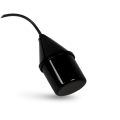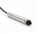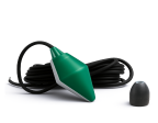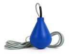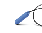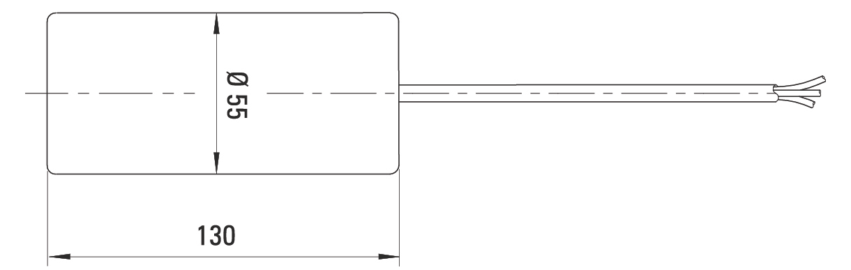
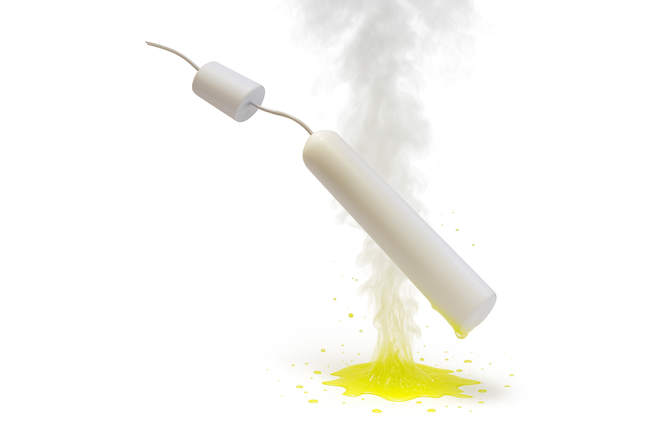
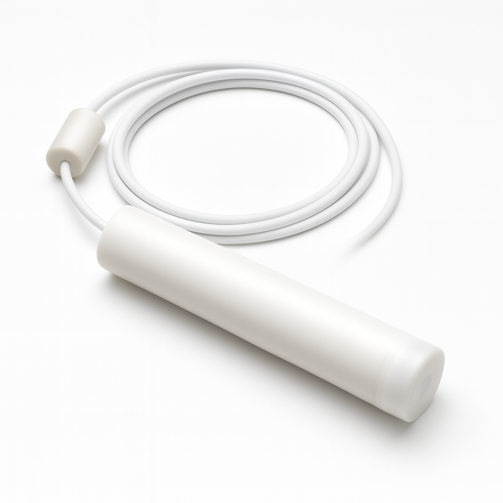
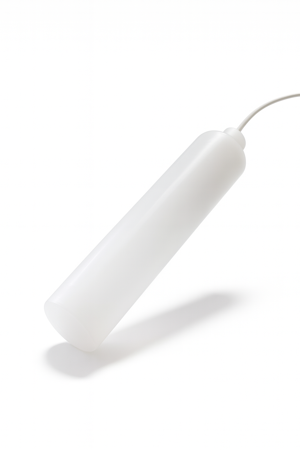
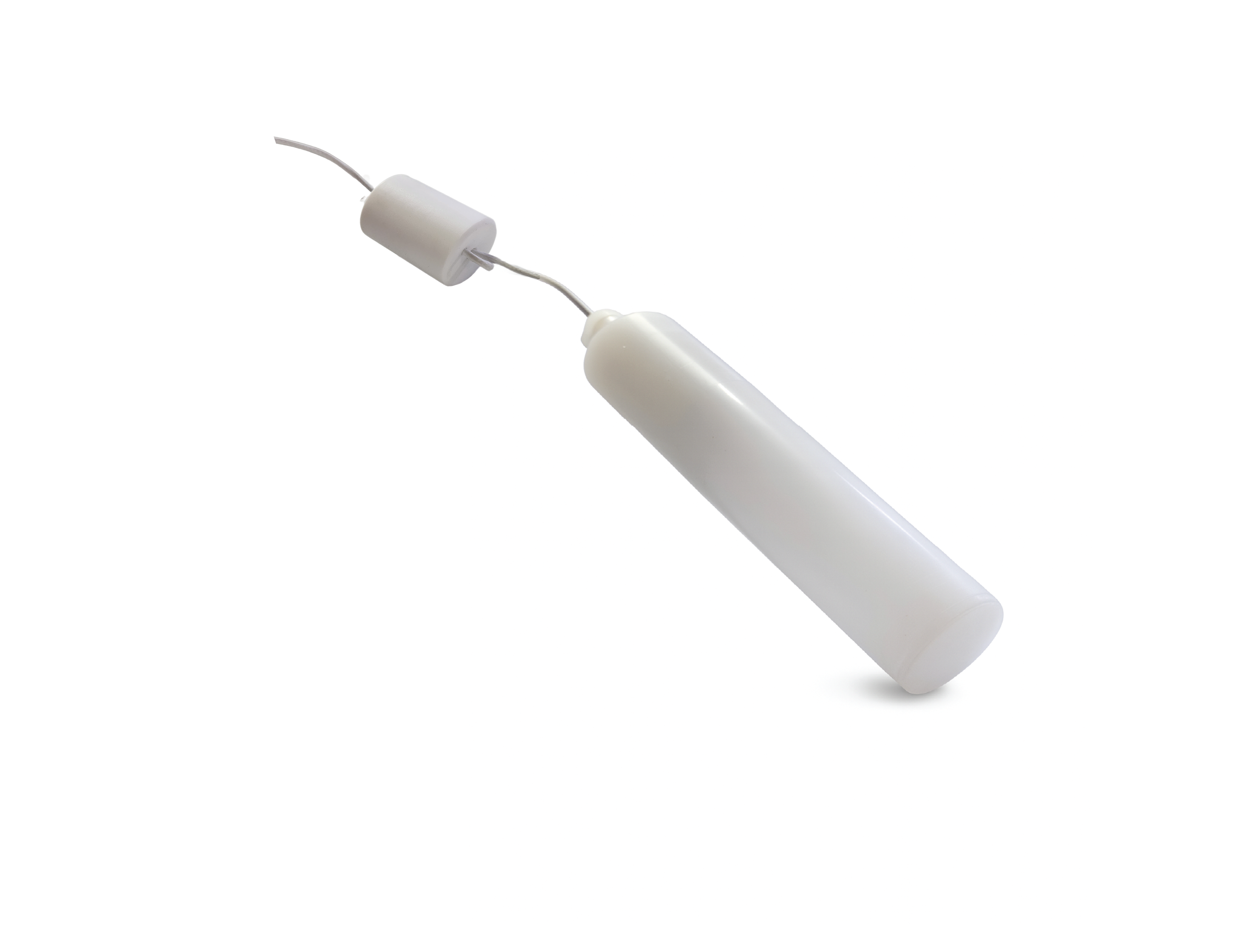

The TUBA 125 C float level switch is a tubular level detector specially designed for the most demanding applications, involving extremely aggressive liquids or high temperatures, up to 125 'C.
Its unique design combines a PTFE cable and a PVDF housing, ensuring exceptional resistance to corrosive chemicals, such as sulfuric acid, toluene or other concentrated industrial liquids.
Supplied with a standard PVDF ballast, the TUBA 125 C tubular level detector ensures a stable rotation point and optimal operation over a wide range of densities.
Thanks to its small diameter (O 40 mm), it can be easily installed in tanks with narrow access or through small side openings, where other level detectors cannot be used.
Robust, accurate and durable, the TUBA 125 C tubular level detector represents the ideal solution for level control in extreme chemical and thermal environments.
Download this documentation and keep the most important information at your fingertips.
pdf : 707.26 KB
|
||||||||||||||||||||||||||||||||||||||||||||||||||||||||||||||||||||||||||||||||||||||||||||||||||||||
|
Drainage or FillingThe TUBA 125 C level detector operates on the principle of tilt level detection.
The float is equipped with a three-conductor cable (COM, NO, NC), allowing the operating mode to be selected during wiring: Used in pairs with another float of the same type, it allows regulation of minimum and maximum tank levels.
|
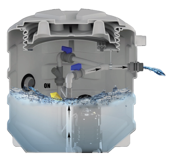
In drainage mode, the level detector triggers the pump start in the high position (overflow protection). An electric current passes through the float to the connected device (control relay, pumps, valves, alarms).
Once the tank is empty, the level switch cuts the electrical circuit to protect the equipment (pumps) in the absence of water in the tank.
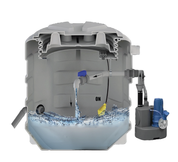
In filling mode, the electrical circuit inside the switch closes (NC) when the switch is in the low position. Thus, the pump starts to fill the tank.
Ballast positioningThe triggering of the float level switch (switching angle) may vary depending on liquid agitation, filling/drainage flow rate, but especially depending on the ballast positioning or fixing point. Indeed, the cable length between the counterweight and the float switch determines the amount of liquid that rises or falls to bring the float switch to change state. You have the possibility to adjust the counterweight on the device cable to optimize its operation. |
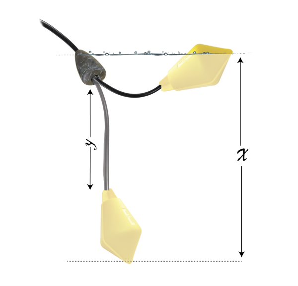
You have the possibility to adjust the counterweight on the device cable, thus the greater the distance between the ballast and the float, the greater the level difference will be, consequently the greater the switching angle will be.
This allows the float to adapt to possible turbulence in the liquid but also allows the float to work in a wide range of densities.
Below are values given for information purposes for the BIP STOP with a minimum and maximum cable length to ensure proper operation:
Min. value Y = 10cm > X ≈ 30-35 CM
Max. value Y = 30cm > X ≈ 60-65 CM
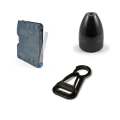
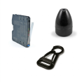
To adjust the ballast on the cable, simply pull on the plastic or resin ballast to unclip it from the clamping ring or O-ring. Then, slide the clamping ring/O-ring to the desired location and replace the ballast on it, so that the weight is locked on the cable.
|
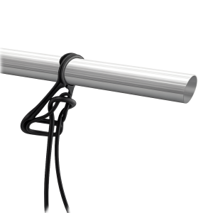
Float fixingThe float level switch can be suspended via the cable sheath, using the FIXCAB cable fixing accessory, which allows proper fixing of the electrical cable at the desired height and allows precise adjustment at any time. Be careful when using clamps or other elements during fixing that can damage the cable and deteriorate the device by allowing water to enter inside the float level switch by capillarity.
|
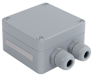
Electrical connectionIn outdoor or humid spaces, the electrical connection of the float level switch must be waterproof and properly insulated in a hermetic box, thus preventing water or other contaminants from entering the cable. This helps prevent water infiltration that could compromise the safety of electrical connections as well as the float's lifespan. The electrical junction box must never be placed inside the tank. The cable and its capillary can be extended using a standard signal cable. We equip our floats with the cable length you want to avoid connections that would impair their operation.
|
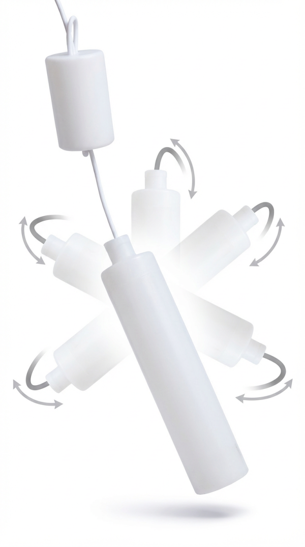
Unlike flat sensors, the TUBA 125C tubular level detector offers omnidirectional detection. Its shape allows it to react to water movements regardless of its position in the liquid.
This ensures more reliable detection, particularly in agitated environments or those subject to turbulence.
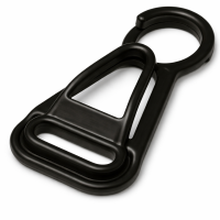
Cable fixing accessory strongly recommended for all suspended floats.
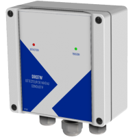
Level control relay with alarm.
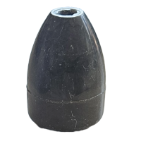
Adjustable ballasts are essential for proper float operation.
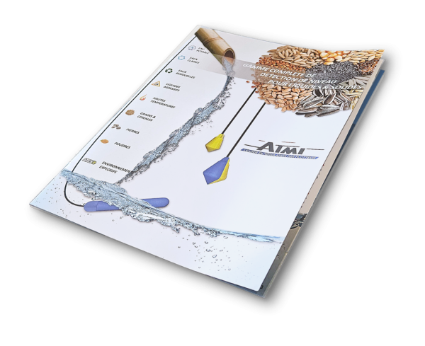
To better define the float level switch adapted to your needs, ATMI offers a wide range of level switches for liquids and solids in various applications.